Intro
The end pieces of the pergola above my deck kept blowing off. I finally lost track of them and decided to 3D print a replacement to keep my skills fresh. I will use this as an opportunity to review my process for 3D printing.
The details
For people like me who don’t really know what they are doing, the kinds of objects you can 3D print is pathetically small. Yes, there are sites like thingiverse.com. But there are so many physical constraints if striking out on your own. If the extruder is pulling the filament horizontally it can only be unsupported for, I forget, 1 cm or so. That may be called a bridge. If you’re going from smaller to wider, the angle of increase cannot be greater than 45 degrees though I think 30 degrees is a safer bet. If you can want to violate either of those contraints you’ll have to include supports which you later saw away (yuck).
So those two constraints, combined, kill just about anything you’d ever want to print.
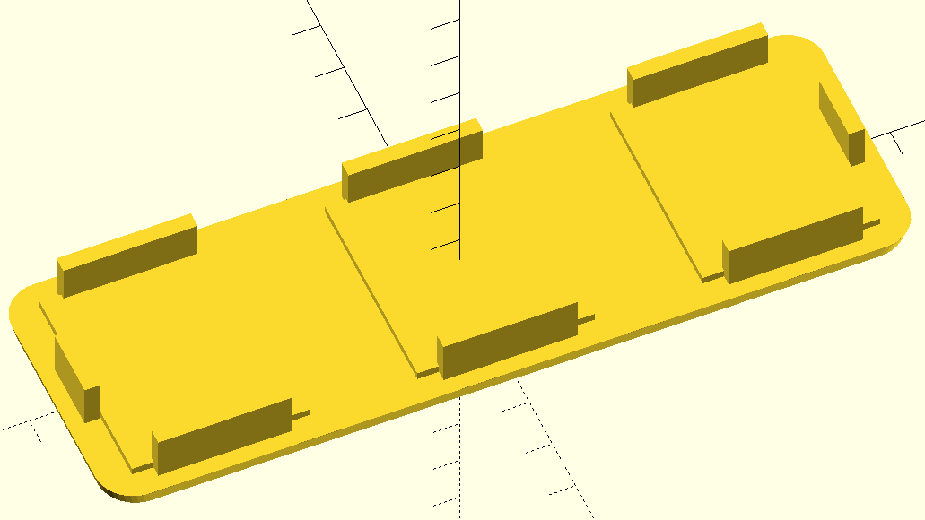
But, amazingly, my endplates could meet the criteria, if I made a slight compromise, so I went for it.
Openscad
I use openscad.org’s software to make a mathematical model of the object, built up from primitive geometric shapes (cubes and cylinders, mainly). When I learned you could write a simple program to generate your figure, and see the results rendered, I was like, sign me up.
Here is my openscad code, with some extra unused stuff left over from a previous design.
// DrJ 4/2020. Parameters in mm
  roundness=7;
  xsize=151;ysize=50;
  innerdelta=20; taperdelta=1.5;
  legthick=3; leglength=25;legheight=12;legoffsety=3;
  xteeth = 106; yteeth = ysize - 2*legoffsety - legthick;
  xhole=126;yhole=66;
  fullthickness=6; taperthickness=3;
  xreinforce=64;yreinforce=38;
  screwrad=1.6;
  divotrad = 5.1/2;
  Hhole = 15;
  screwholes=32.1;
  cablewidth = 16; cableheight = 10; cablex=16;
  cabley=-13;
  tinypropindent=9;
  // min facet angle and facet size (mm)
  $fa = 1.1; $fs = 1.1;

  hull() {
  nice_rectangle(roundness,xsize-taperdelta,ysize-taperdelta);
  translate([0,0,taperthickness]) nice_rectangle(roundness,xsize,ysize);
  }

 // legs
 for(x=[-1,0,+1])
     for(y=[-1,+1])
        translate([x*xteeth/2,y*yteeth/2,legheight/2])
          cube([leglength,legthick,legheight],center=true);
 for(x=[-1,+1])
        translate([x*(xsize-2*legoffsety - legthick)/2,0,legheight/2])
          cube([legthick,leglength-12,legheight],center=true);
// thickeners
for(x=[-1,0,+1])
   translate([x*xteeth/2,0,taperthickness])
    cube([leglength+8,yteeth-1,taperthickness],center=true);
  //
  module nice_rectangle(roundness,xsize,ysize)
  {
   xcyl=xsize/2 - roundness;
   ycyl=ysize/2 - roundness;
   height=.02; // basically 2D - expect to
  // be used within a convex hull

   union()
   {
    for(x=[-1,+1])
      for(y=[-1,+1])
        translate([x*xcyl,y*ycyl,0])
          cylinder(r=roundness,h=height, center=true);
    cube([xsize, ysize-2*roundness, height], center=true);
    cube([xsize-2*roundness, ysize, height], center=true);
   }
  }
STL
You always make mistakes. The question is if you have the trouble-shooting skills to catch them before committing to printing… Anyway, when satisfied, render your object (F6), only then can you export to STL (stereolithography), which I guess is a universal description language.
Cura
Then you need a slicer! I think that translates your shape into movements that the 3D printer needs to make to lay down the filament, layer by layer. So import your STL file into Cura.
I think I set up Cura last year. I don’t want to mess with it. And don’t start playing with your model. It’ll do funny things to it. Just save as GCode. That’s it. Cura kindly estimates how long your print will take, and how much filament it will use up.
Cura will every time propose to upgrade itself. Don’t waste your time. Just say no. If all you’re doing is using it to turn STL into GCode you don’t need the latest.
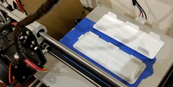
Anet a8 printer
It can be a royal pain to adjust the Z axis. Usually you have to adjust all four corners so that pulling a paper through gives just a little friction. The screws and assembly is so bad that you are constantly shifting between over-correcting and under-correcting. In this case I divided the problem in two because the plate was so narrow I just adjusted for the two sides, not all four corners, which is a nightmare. And I’m a little ahead of myself, but I have to say that this approach worked brilliantly.
Transfer the file to the micro SD card. Print, and enjoy! More fun is printing something with a lot of holes. The printer makes the coolest electric sounds as it quickly shuttles back and forth and to and fro. This endplate is pretty boring by comparison and mostly consists of long stretches of material.
End result
With its long flat section, the thing really adheres to the plate, unfortunately. I slightly nicked a corner prying it off with a screwdriver. But I think that beats the alternative of it not adhering to your plate. I’ve seen that once – and the printed thing just gets dragged around, which is fatal.
My piece came out a couple millimeters short in both dimensions. Still functional because of what it is, but still something I need to understand better.
Industrial design
I take it for granted that the PLA I’m printing is not as strong as the original plastic, so I should compensate by making edges thicker than needed. But I have to say the thing came out quite rigid and strong. This cheap 3D printer – if you treat it right – produces some high-quality output!
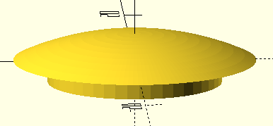
Bolt hole cover
In June I decided to print a bolt hole cover, also for the pergola above my deck. Modelling was pretty easy. I used a sphere for the first time to create the curved shape of the cover. Then I had to “get rid” of the rest of the sphere so I swallowed the unwanted portion of it up with a giant cylinder.
Here’s the openscad code.
// DrJ 6/2020. Parameters in mm

  innerR=8;outerR=11;plugHeight=2;
  epsilon=0.4;upperHeight=2.5;
  sphereR=26; big=50;
  tinyR=1;
 // min facet angle and facet size (mm)
  $fa = 1.1; $fs = 1.1;


  difference() {
  translate([0,0,-(sphereR - upperHeight)]) color ([0.2, 0, 0]) sphere(r=sphereR);
  translate([0,0,-big/2]) cylinder(r=big,h=big,center=true);

  }
  translate([0,0,-plugHeight/2]) cylinder(r=innerR,h=plugHeight, center=true);
I installed Cura v. 3.2.1 to make sure I had a version with support for supports, ha, ha. Most views don’t even show the support. I made sure I had it generate supports. Then I found that the layers view, when you drag it through the layers, shows the supports it will make. Some support options definitely would not have worked, by the way, namely, lines.
But, basically, supports are basically impossible to remove. I pried at it and rubbed with sandpaper but my vague hope that the supports might pop off were badly misplaced. The thing looks like a button. But fortunately the plug part was shallow so I just super-glued the thing onto my pergola and it looks like the real deal at a glance. In fact it looks better.
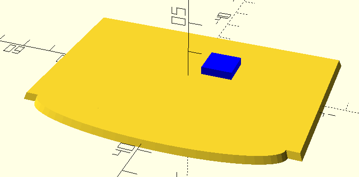
Mailbox plate
If I thought I was a whiz at this sort of thing, this mini-project proved me wrong. I was going to add a semi-circle at the bottom of a rectangle, and work through Pythagorean’s theorem to find the unknowns. I was just spending too much time and really, eye-balling it was more effective. And a more desirable shape was an ellipse. So the good ones make these parameterized models, but I find it’s not so easy and when you want to bang out some custom part quickly, it may not make sense.
There was a gaping hole in my mailbox post. This plate covers it up. Here’s the code.
// DrJ 7/2020. Parameters in mm
xsize=87;ysize=55; ylowest=65;
taperthickness=2.3;
// min facet angle and facet size (mm)
$fa = 1.1; $fs = 1.1;
xreduce=8;
union(){
linear_extrude(height = taperthickness, center = true, convexity = 20, twist =0, slices = 20, scale = .98, $fn = 30){
square(size=[xsize,ysize],center=true);
}
linear_extrude(height = taperthickness, center = true, convexity = 20, twist =0, slices = 20, scale = 0.98, $fn = 60){
translate([0,ysize/2,0]) resize([xsize-xreduce,2*(ylowest-ysize)]) circle(d=30);

}
}
// bump out. Color blue.
translate([-xsize/2+35,-ysize/2+20,taperthickness]) color([0,0,1]) cube([10,10,2.9],center=true);
What techniques I learned from this simple mailbox plate project
I used the linear extrude method for the first time. Very useful. So, shapes like squares and cirlces (or ellipses) extruded along the Z-asix. My first effort did not include the bump-out, which I needed as a spacer. So I learned that you don’t always have to re-level after every print and this was the first time the dang filament didn’t break on me between print jobs – because I acted within 24 hours. I even re-used the blue tape. All real time-savers. So I used the 3D printer the way you imagine it to be – just there to print stuff, not to worry about fixing all the time.
I also had a reject – a first attempt without the bumpout. I kept it to test the breaking strength. So the thickness is 2.3 mm, right (I have to get calipers!)? It’s pretty darn strong. I was probably applying 10 pounds of force and it was hardly budging. Each layer prints orthogonally and a piece this thin is solid material.
Bird feeder C ring
I have a backyard bird feeder which hangs too low – I fear a squirrel could jump to it. So I wanted a way to shorten the hang by winding the wire around something that will stay. So I designed a C-shaped ring thing. works great. This is a first time for me for using a rotate extrude. I had to chop off the bottom of the ring so that I would not need supports. This is my shortest code yet, and least paraemerized. It’s just easier when you want to knock something out quickly…
// DrJ 7/2020. Parameters in mm
// min facet angle and facet size (mm)
$fa = 1.1; $fs = 1.1; $fn=100;
difference(){
rotate_extrude(angle=348,convexity = 10)
translate([20, 0, 0])
circle(r = 6);
translate([0,0,-9]) cube([60,60,10],center=true);
}
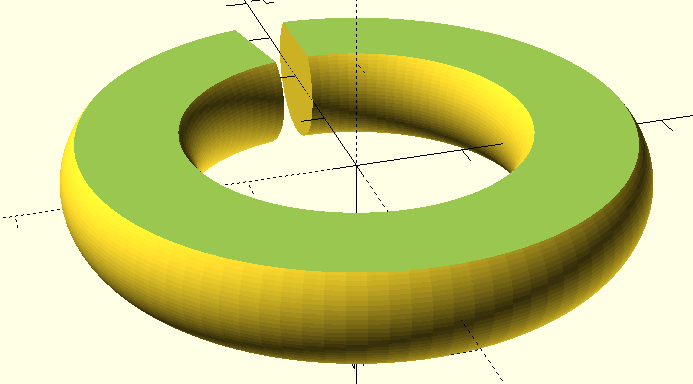
This is my first piece with interior fill. The bird feeder is pretty heavy – 10 pounds. but this little C ring is plenty strong for entwining the hanging string.
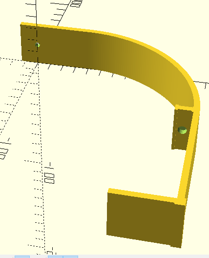
Curved TV bracket
The code
// DrJ 12/2019. Parameters in mm
  z=32;
  thickness=4;
  a=38; // 1 1/2" - the lip
  S=174; //6 7/8" - how far to come out
  m=127; // 5 3/32" - hole to TV edge
  n=13; // 1/2" extra beyond screw hole
  o=m-S/2;
  r=S/2;
  Rscrewhole=2;
  t=85; //restraint y from inner claw
  u=S-thickness-t;
  Rthole=3;
  xt=12;

  reinforce=10;
  bigthick=thickness+1;

  // min facet angle and facet size (mm)
  $fa = 1.1; $fs = 1.1;

  difference() {
    translate([-n,0,0])
    cube([n+o,thickness,z]);
    translate([0,thickness,z/2]) rotate([90,0,0]) cylinder(r=Rscrewhole,h=thickness*3);
  }
  // staircase
  translate([m-a,-S,0])
    cube([a+thickness,thickness,z]);
  translate([m,-S,0])
    cube([thickness,S/2,z]);
  //reinforce the corner
  shim=bigthick-thickness;
  translate([m-shim,-S-shim,0]) cube([bigthick+shim,shim,z]);
  translate([m,-S-shim,0]) cube([bigthick,bigthick+shim,z]);
  // curved section
  translate([o,-S/2,0]) {
      rotate_extrude(angle=90,convexity=10){ translate([S/2,0,0]) square([thickness,z]);}
  }
  // restraint
  translate([m-xt,-u,0]) {
      difference() {
          cube([xt,thickness,z]);
          translate([2*Rthole,thickness,z/2]) rotate([90,0,0]) cylinder(r=Rthole,h=thickness*3);
  }}
  //thickeners
  translate([m-1,-u-1,0]) cube([2,thickness+2,z]);
  translate([m-xt,-u-1,0]) cube([2,thickness+2,z]);
Waffle tile
// DrJ 12/2019. Parameters in mm


  barthick=6;
  shaveamount=2;
  shavedthick=barthick-shaveamount;
  lip=7;
  lipandextra=lip+3;
  radius=1.5;
  z=7;
  ytot=190;
  //y=ytot-2*lip;
  y=ytot;
  nbars=5;
  xstep = (ytot-2*lipandextra-nbars*barthick)/(nbars-1) + barthick;

  // min facet angle and facet size (mm)
  $fa = 1.1; $fs = 1.1;
  difference() {
   wafer();
   // half material for tesselation
   halfbar=barthick/2;
   translate([halfbar,-y+lip,-1]) wafer(z+2);
   translate([-halfbar,y-lip,-1]) wafer(z+2);
   translate([y-lip,halfbar,-1]) wafer(z+2);
   translate([-y+lip,-halfbar,-1]) wafer(z+2);
   // holes
   ydis=lipandextra-lip/2;
      echo (ydis);
   translate([0,-ydis,z/2]) rotate([0,90,0]) cylinder(r=radius,h=y);
   translate([0,y-2*lipandextra+ydis,z/2]) rotate([0,90,0]) cylinder(r=radius,h=y);
   translate([lipandextra-ydis,0,z/2]) rotate([-90,0,0]) cylinder(r=radius,h=y);
   translate([y-lipandextra+ydis,-1,z/2]) rotate([-90,0,0]) cylinder(r=radius,h=y);
   // shave off material by sitting cube on top
   cubelen=y-2*(lipandextra+shavedthick);
   translate([lipandextra+shavedthick,shavedthick,z-shaveamount]) cube([cubelen,cubelen,z]);
  }

  //rotate([-90,0,0]) cylinder(r=radius,h=y);

  module wafer(zwafer=z){
  for(xs=[lipandextra:xstep:ytot]){
      translate([xs,-lipandextra,0]) bar(zwafer);
  }
  translate([y,0,0]) rotate(90) {for(xs=[0:xstep:ytot]){
      translate([xs,0,0]) bar(zwafer);
  }
  }
  }

  module bar(zheight=z) {
      cube([barthick,y,zheight]);
  }
Router platform
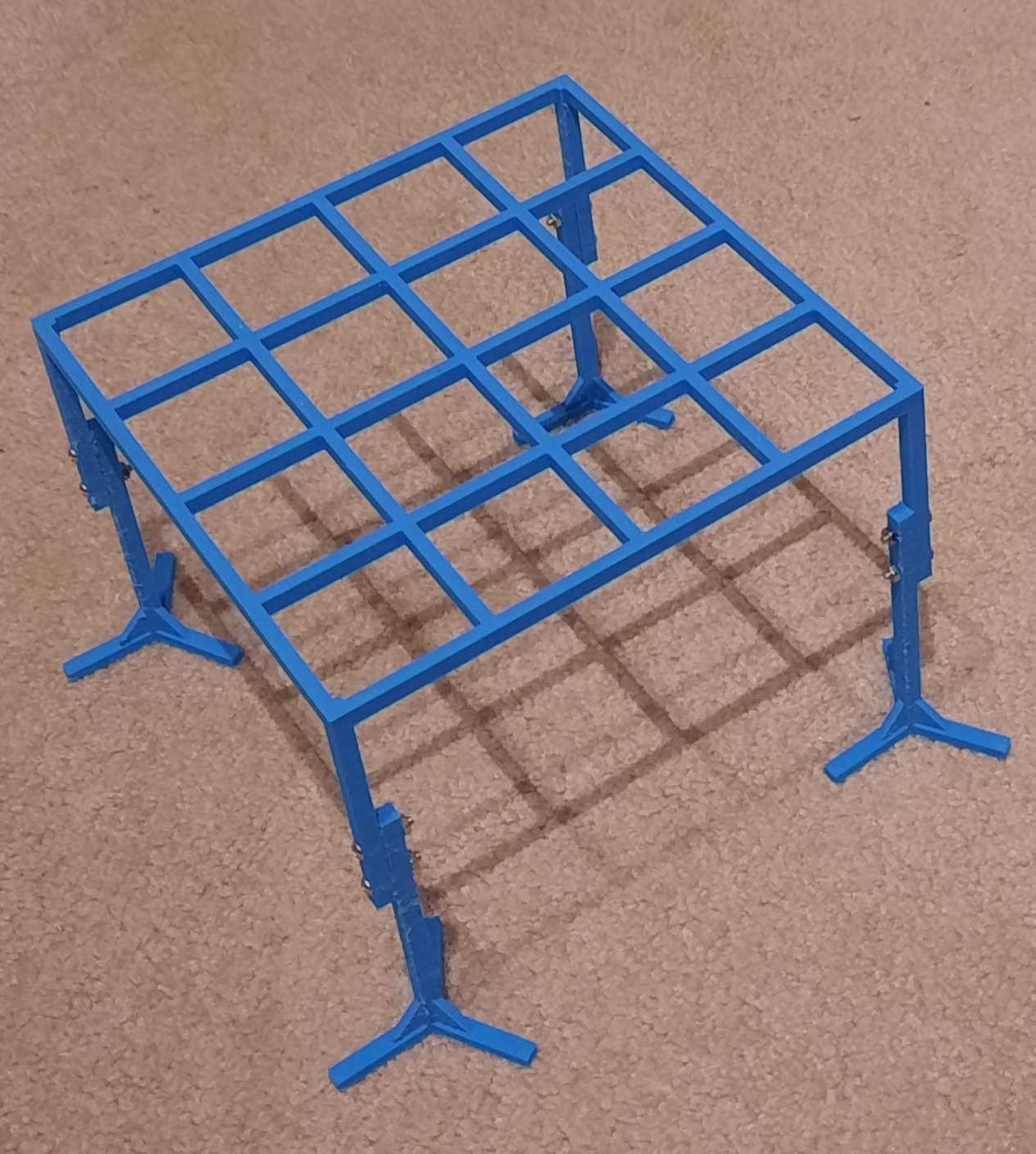
This router platform consists of two separate printing jobs. Here are the bird legs. Note these openscad files contain a bunch of unneeded detritus.
// DrJ 12/2019. Parameters in mm
  barthick=4;
  legthick=6;
  lip=0;
  lipandextra=lip+0;
  radius=2.0;
  z=6.5;
  zleg=100;
  birdleglen=33;
  step=birdleglen*1.1;
  number=4; // number to print out
  max=number*step-1;
  birdthick=4;
  zlegwafer=80;
  halfleg=38;
  ytot=190;
  brace=birdleglen/1.9;bracethick=3;
  //y=ytot-2*lip;
  y=ytot;
  nbars=5;
  xstep = (ytot-2*lipandextra-nbars*barthick)/(nbars-1) + barthick;

  // min facet angle and facet size (mm)
  $fa = 1.1; $fs = 1.1;
  for(trans=[0:step:max]){
      translate([trans,trans,0])
  birdleg();}

  module birdleg() {
      difference(){
      mainleg();
          // holes
          boost=zleg-zlegwafer;
          for (zhole=[boost+.9*zlegwafer,boost+.7*zlegwafer]) {translate([-legthick/2-1,0,zhole])
              rotate([0,90,0]) cylinder(r=radius,legthick*2);
      }
  }}
  module mainleg() {
      zcube([legthick,legthick,zleg]);
      // bird feet
      for(r=[0,120,240]){rotate([0,0,r]){
   ycube([birdleglen,legthick,birdthick]);
       // brace
     rightangle([brace,bracethick]);
    //ycube([brace,bracethick,brace]);
   }
      }}
      module ycube(dims){translate([0,-dims[1]/2,0]) cube(dims);
      }
  module zcube(dims) {
     translate([-dims[0]/2,-dims[1]/2,0]) cube(dims);
  }
  // braces
  module rightangle(dims) {
      difference() {
      ycube([dims[0],dims[1],dims[0]]);
      hyp=1.5*dims[0];
      translate([dims[0],-1,0]) rotate([0,-45,0]) ycube([hyp,2*dims[1],hyp]);
  }}
That was the bird legs. Here is the single wafer:
// DrJ 12/2019. Parameters in mm
  barthick=4;
  legthick=6;
  lip=0;
  lipandextra=lip+0;
  radius=2.0;
  z=6.5;
  zleg=80;
  halfleg=38;
  ytot=190;
  //y=ytot-2*lip;
  y=ytot;
  nbars=5;
  xstep = (ytot-2*lipandextra-nbars*barthick)/(nbars-1) + barthick;

  // min facet angle and facet size (mm)
  $fa = 1.1; $fs = 1.1;
  difference() {
   wafer();
   // half material for tesselation
   halfbar=barthick/2;
   translate([halfbar,-y+lip,-1]) wafer(z+2);
   translate([-halfbar,y-lip,-1]) wafer(z+2);
   translate([y-lip,halfbar,-1]) wafer(z+2);
   translate([-y+lip,-halfbar,-1]) wafer(z+2);
  }
  // legs
    for(xl=[0,ytot-legthick]){
     for(yl=[0,ytot-legthick]){
          translate([xl,yl,0]) {
          difference(){cube([legthick,legthick,zleg]); for (zhole=[.9*zleg,.7*zleg]) {translate([-1,legthick/2,zhole])
              rotate([0,90,0]) cylinder(r=radius,legthick*2);
          };
      }}}}


  module wafer(zwafer=z){
  for(xs=[lipandextra:xstep:ytot]){
      translate([xs,-lipandextra,0]) bar(zwafer);
  }
  translate([y,0,0]) rotate(90) {for(xs=[0:xstep:ytot]){
      translate([xs,0,0]) bar(zwafer);
  }
  }
  }

  module bar(zheight=z) {
      cube([barthick,y,zheight]);
  }
Wine bottle holder
A friend printed this for me using PETG material. It seems pretty nice. And my design works really well for my singular purpose (shown in picture below).
 // DrJ 6/2021. Parameters in mm

  barthick=6;

  legthick=6;

  height=94; // approximate – remeasure

  apart=50;

  innerringD=32; // 1.25″

  boost=innerringD/2 + 4;
  fromend=7; // for topbar screwholes

  nexthole=26.2;

  topbarlen=38 + nexthole/2 + fromend; // 1.5″ back from rod center

  radius=1.8; // works with m3 screws

  // min facet angle and facet size (mm)

  $fa = 1.1; $fs = 1.1;
  //lie the whole thing flat for printing with no supports

rotate([0,90,0]){

zigzag(); translate([0,apart,0]) zigzag();

crossbar();

gallows();

  }
module zigzag() {

    zcube([legthick,legthick,height+boost]);

    // topbar

    xtrans=-(topbarlen-legthick/2);

    difference(){

    translate([xtrans,0,height-barthick/2]) xcube([topbarlen,legthick,barthick]);

        {translate([-topbarlen+fromend,0,height-barthick]) {

            cylinder(r=radius,legthick*2); translate([nexthole,0,0]) {cylinder(r=radius,legthick*2); }

        }}

    } // end difference

}

module zcube(dims) {

     translate([-dims[0]/2,-dims[1]/2,0]) cube(dims);

  }

 module xcube(dims) {

     translate([0,-dims[1]/2,-dims[2]/2]) cube(dims);

  }

   module ycube(dims) {

     translate([-dims[0]/2,0,-dims[2]/2]) cube(dims);

  }

 module crossbar() {

     translate([0,0,legthick/2]) ycube([legthick,apart,legthick]);

 }

 module gallows() {

     difference(){
     difference(){

     translate([0,apart/2,height+boost]) rotate([0,90,0]) cylinder(h=legthick,d=apart,center=true);

     translate([0,apart/2,height+boost]) rotate([0,90,0]) cylinder(h=legthick+1,d=innerringD,center=true);}
     translate([-apart/2,0,height+boost]) cube([apart,apart,apart]); }

 }

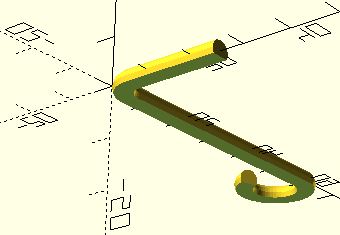
Birdfeed loosener
I need a thingy to loosen my birdfeed. I had been using an allen wrench, but I lost it and it wasn’t quite the right shape – nowhere to put it. So I designed this simple fit-for-purpose object. It features a hook for hanging, a rounded corner and a flat bottom for easy printing.
 // DrJ 7/2021. Parameters in mm

  height=60; // longest section

  length=25; // section into feeder

  hookdiam=6.5;

  angle=250; // extrude angle

  radius=2.1; //

  corn2=5; //looks good…

  // min facet angle and facet size (mm)

  $fa = 1.1; $fs = 1.1;
  module drawandremove() {

        difference(){

      drawitup();

      translate([0,0,-corn2]) zcube([2*corn2,corn2,2*corn2]);}

  // now for the rounded corner – similar to the hook

  roundcorn();

     }

     module drawandremove2(){

         difference(){drawandremove();

         translate([0,radius/2,0]) ycube([200,200,200]);}}

  module drawitup(){

  cylinder(r=radius,h=height);

  translate([0,0,0]) rotate([0,90,0]) cylinder(r=radius,h=length);

  // hook

  hook();

  }

  module hook() {  translate([-hookdiam,0,height-radius]) rotate([90,0,0])

  rotate_extrude(angle=angle,convexity = 10)

      translate([hookdiam, 0, 0])

circle(r = radius);

  }

   module roundcorn() {

     translate([corn2,0,corn2]) rotate([90,180,0])

  rotate_extrude(angle=90,convexity = 10)

      translate([corn2, 0, 0])

circle(r = radius);

  }

  //lie the whole thing flat for printing with no supports

rotate([-90,0,0]){

drawandremove2();

  }
module zcube(dims) {

     translate([-dims[0]/2,-dims[1]/2,0]) cube(dims);

  }

 module xcube(dims) {

     translate([0,-dims[1]/2,-dims[2]/2]) cube(dims);

  }

   module ycube(dims) {

     translate([-dims[0]/2,0,-dims[2]/2]) cube(dims);

  }
Utensil drawer block
This thing keeps my utensil holder from sliding within the drawer. I began by using chatgpt, or I should say trying to use. It was helpful to get me started, but more complicated things seemed to totally elude it.
// DrJ 1/2025. Parameters in mm

// Dimensions of the box

width = 110;

length = 150;

thickness = 3;

epsilon = 1;

brace_angle = 30;

brace_z = 20;

spacing = 53; // Spacing between the lines in the criss-cross pattern

line_thickness = 4; // Thickness of the lines in the pattern

leg_height = 53; // Height of the legs

leg_width = 6; // Width of the legs

leg_length = 10; // Length of the legs

//width = width – line_thickness; // correction

side_height = thickness; // Height of the side leg

side_width = width; // Width of the side leg

side_length = 10; // Length of the side leg

module leg() {

    // Create a leg

    cube([leg_width, leg_length, leg_height]);

}

module shave_cube(){

    translate([0,-epsilon,thickness]){cube([side_width,side_length+2*epsilon,leg_height]);};

}

module leg_brace() {

    // Create a leg brace

    difference(){

    translate([0,0,-brace_z]){rotate(a=[0,brace_angle,0]){cube([leg_width, leg_length, leg_height]);}};

    shave_cube();

    }

}

module side_leg() {

    // Create a leg

    cube([side_width, side_length, side_height]);

}

module criss_cross_pattern() {

    for (i = [0 : spacing : length]) {

        // Horizontal lines

        translate([0, i, 0]) {

            cube([width, line_thickness, thickness]);

        }

    }

    for (i = [0 : spacing : width]) {

        // Vertical lines

        translate([i, 0, 0]) {

            cube([line_thickness, length, thickness]);

        }

    }

}
// Create the criss-cross box

criss_cross_pattern();

// Add legs at two corners

translate([0, 0, -(leg_height-thickness)]) {

    leg(); // Leg at the bottom-left corner

}

translate([0, length – leg_length, -(leg_height-thickness)]) {

    leg(); // Leg at the bottom-left corner

}

// add stronger sides

translate([0, 0, 0]) {

    side_leg(); // Leg at the bottom-left corner

}

translate([0, length – side_length, 0]) {

    side_leg(); // Leg at the bottom-left corner

}

leg_brace();

translate([0,length – side_length,0]){

    leg_brace();}

//shave_cube();
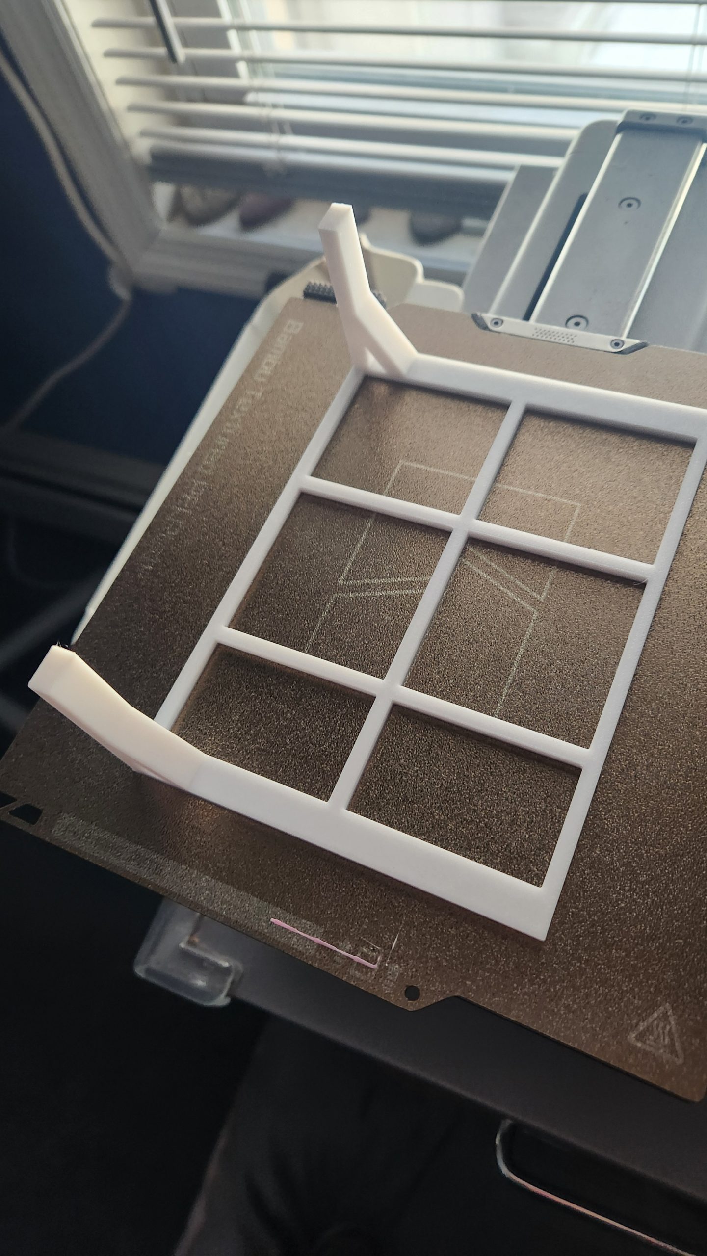
I had a friend print it out who does 3d printing as a service.
Some learnings from my experience
If you have problems with your USB stick
I should be embarrassed to admit this, but I’m otherwise tech-savvy so I am not. I put my orange USB stick 9flash drive) into my computer in order to copy over my latest GCode, and the computer made that typical Windows double sound which shows you’ve plugged something into a USB port, but the F: drive would not show up no matter what I did.
Well, turns out I had left the micro SD card behind in the printer! It has to be inserted into the back of the USB stick. Duh, right? In my defense I hadn’t printer anything in months and I simply forgot the setup.
How frequently should the print bed be leveled?
I thought maybe you have to do it before every print job. But you see that TV bracket up above? I had to print out five of them as I continued to refine the design (and I was really trying to not be wasteful!). They take five – six hours to print. i would simply print one out after another without re-leveling the print bed. No issues. I did have to press down on my painters tape, which bubbled up where there was contact with the PLA.
Does printing thin, vertical pieces work OK?
Yes. I did a 3 mm thick piece about 1 1/2″ high – no issues. Then I switched to 4 mm and also no problems of course.
How large can holes be in the “wrong” (Z) dimension?
Again in that TV bracket I had holes of 4 mm and 6 mm in diameter in the z dimension. Do the rules about “bridges” apply? I have no idea, but they’re fine. Not smooth as glass, but sub-millimeter deviations from perfection. Definitely fine for passing screws through. maybe just a tad rougher in appearance than the surrounding surfaces. At some point as you scale up the radius, the top of a hole is a bridge, so failure has to occur, just thinking through this logically.
Do the belts and motors of the printer get loose after a few prints and after a year?
Not really. Mine still printed great after a year and light usage. I still can’t believe the quality that comes out in fact.
How uniformly does the print bed have to be leveled?
We all know you pull a paper through between nozzle and print bed and adjust until you meet resistance. What if one corner has more resistance than the rest? I would say it doesn’t matter. If you’ve ripping up the paper – that’s an issue, but the difference between a little resistance and more resistance should not be sweated. On my printer I assert it’s impossible to make the bed completely uniform. Also see the tip below about the print bed. I also recommend not to move the printer after leveling the print bed. I believe it will deform from even small movement. But I have printed six 50 gram jobs, one after the other, without re-leveling, which is great. The sixth job, however, totally failed. But see the next tip about watching the beginning of the print job.
Watch the beginning of the print job
I have lost prints twice. First time it was that the heated filament printed out a bit, but then the stuff on the print bed just started to be dragged around. Second time I printed a long, narrow piece. One end of it started to curl upwards like a water ski. I re-adjusted the print bed level no that side. Those things are going happen at the beginning of the print job if it happens at all. So watch the beginning of the printing for proper printing.
Are there differences in PLA?
Surprisingly, the answer seems to be definitely yes. The white PLA which came with printer seems to be much more fragile than the black stuff I bought (see link below). I’ve been told that the filament becomes brittle with exposure to air. With my white PLA it kept breaking off after a few days between print jobs, no matter what I did! The black stuff, by contrast, did not break off once! Not even when left in place for months!
Does PLA deform under tension or sheer forces?
See that C ring above? That was printed with the black stuff and used outside. It stretched noticeably over the course of the summer. perhaps a combination of the summer heat plus the tension. But whatever, the printed parts feel nice and rigid when first printed out, but they will permanently deform! Engineering plastics could probably address that, but I have no practical experience with them.
How to yank the finished print away off the print bed
You’ll break your fingernails trying to pry your printed masterpieces off the print bed. Of course I use blue painters tape over the print bed. I have settled on a technique where I use a needle nose pliers. Pull firmly while simultaneously pushing down with the other hand on the print bed. All my stuff, which is pretty dimensional, pops right off like that, and the tape is ready for another print – it is not ruined.
Thin strips are padded
With my setup, anyway, my thin vertical pieces are consistently coming out over the specified dimensions by about .5 mm. This overage can be important in a lot of projects. Similarly, holes are produced smaller than the specified dimensions, though I don’t know by how much, but seems to be in the range .5 – 1.0 mm. I know these things because I bought an inexpensive caliper!
How many parts of this type can you get from your spool of PLA?
Most (all?) of my projects involve fourth-grade level math, honestly. No algebra. Maybe a tiny hint of trigonometry. Anywya, Cura tells you how much PLA your printout will use. My TV bracket was around 50 grams. This is painfully obvious, but just to put it out there, do the math. If you have a 1 KG (= 1000 grams) spool of PLA and each thing you’re printing takes, e.g., 50 grams, you can print 1000 grams / (50 grams per piece) = 20 pieces.
Filament stops coming out in the middle of the printing – what to do?
I am currently suffering from this. I think my nozzle is too full of crud. I have no idea how to fix it (no time to research this).
I don’t enjoy tinkering with my finicky 3D printer. Is there a “3D printing as a Service” business?
I have been told there is not. People send ridiculously impossible things to print, expecting miracles. Perhaps someone will soon solve this issue (by qualifying all print jobs beforehand)? OK. There is a very commercial service. But it is way too expensive for hobbyist. Probably a minimum of $100. See the references for another suggestion.
Time-saving tip for leveling the print bed
My anet a8 prints great once I get it set up. But that setup – boy is it a pain. Leveling the print bed being the absolute worst. Because, if you follow their advice and adjust each corner, well, they don’t seem to stay and you end up reversing your direction on the screws of the print bed. Or you’ll get one corner and then the corner you had just done will be off.
But think about it. For these small jobs, it only has to be level at the center. So, the heck with it, just make sure when you drag a piece of paper with the nozzle at the center that it has a bit of resistance, and don’t stress about what happens at the four distant corners. You will maintain your sanity this way.
Conclusion
I found the missing piece after printing this piece out, as luck would have it. BUT, then I found another place, right against the side of the house, that was never covered, but could have been. So I slapped my printed part there – it worked great!
A subsequent bolt hole cover project revealed that supports are nasty and basically impossible to remove. Yet the design was such that the thing worked anyways with a little superglue.
A plate to cover a hole in the mailbox post came next, and then a ring with a little slit for my bird feeder. Those two use an extrusion method.
You have to render your model or else export to STL does absolutely nothing, and also does not show an error, except in the console, which you may not be showing.
I learned quite a lot doing the curved TV bracket project. I shared my learnings.
References and related
3D-printing-as-a-service
I’ve recently met the guy behind this Etsy shop: GizmosWidgets – Etsy and I have used his service, which is great, very personable. And only $5 for basic stuff! And he used PETG which he explained would be stronger than alternatives such as PLA.
If you are lucky enough to live in Oak Creek, Wisconsin, or really anywhere in Milwaukee county, you have it! And it’s really cheap – $.05/gram. https://oakcreeklibrary.org/3d-printer/
As for the rest of us, we have to encourage our local libraries and community colleges to get with the program. I think it’s coming, so make sure your interest is known.
This 3D printing service may be the most suitable for engineerss: https://www.sculpteo.com/ . My modest wine bottle holder would cost $27 in their cheapest configuration (SLS plastic PA12). But at least their service looks really legit and gives you lots of options.
This was the anet a8 printer. I don’t think it’s sold any longer, or not the cheapo $139 version which I was lucky enough to get. In fact someone bought one on my recommendation, parts were missing, and he never could get the missing parts. https://www.amazon.com/gp/product/B01N5D2ZIB/ref=ppx_yo_dt_b_asin_title_o01_s00?ie=UTF8&th=1
Good PLA: https://www.amazon.com/gp/product/B00J0ECR5I/ref=ppx_yo_dt_b_search_asin_title?ie=UTF8&psc=1&fpw=alm
OpenScad
The program I use to generate my designs is Openscad. It’s free and still being actively developed. It’s great if you know a bit of scripting and a bit of geometry. https://openscad.org/
This is a great tutorial for openscad and constructive solid geometry: http://www.tridimake.com/2014/09/how-to-use-openscad-tricks-and-tips-to.html and this openscad cheat sheet is a compact listing of all functions and syntax.
This $7 caliper is simply great, and a must have for anyone doing more than a few printouts: https://www.amazon.com/gp/product/B07VSVMWTJ/ref=ppx_yo_dt_b_search_asin_title?ie=UTF8&psc=1
Lots of free 3D designs are available at Thingiverse: https://www.thingiverse.com/
But there are a lot of other great 3D designs out there beyond just Thingiverse. This site introduces lots of these resources with example pictures from printed models.
Cheap Screws and Nuts
I bought this box with dozens of m3 screws and nuts for $11: Amazon.com: Sutemribor 320Pcs M3 Stainless Steel Button Head Hex Socket Head Cap Bolts Screws Nuts Assortment Kit + Wrench: Home Improvement
Network diagram as code using Python: if you like openscad and need to build network diagrams then you should check out this post!