Intro
A friend bought a bunch of parts and thought we could work on it together. He wanted to reproduce this project: Raspberry Pi Audio Spectrum Display – Hackster.io
So of interest here is that it involved a 64×64 LED matrix display, and a “hat” sold by Adafruit to supposedly make things easier to connect.
Now I am not a hardware guy and never pretended to be. When we realized that it required soldering, I bought those supplies but I didn’t want to be the one to mess things up so he volunteered for that. And yes, it was a mess.
Equipment
See later on in the post for the equipment we used.
The story continues
Who knew that gold on the PCB could be ruined so easily after you’ve changed your mind about a soldered joint and decided to undo what you’ve done? The experience pretty much validated my whole approach to staying away from soldering. So we ruined that hat and had to order another one. While we waited for it I developed a certain strtategy to deal with the shortcomings of the partially destroyed hat. See the section at the bottom entitled Recipe for a broken hat.
Comments on the project
I don’t think the guy did a good job. Details left out where needed, extra stuff added. For instance you don’t need to order that Firebeetle – it’s never used! Also, I’ve been told that his python isn’t very good either. But in general we followed his skimpy instructions. So we ordered the LED matrix from DFRobot, not Adafruit, and I think it’s different. In our case we did indeed follow the project suggestion to wire the 2×8 pin as shown in their (DFRobot’s) picture, leaving out the white wire. Once we soldered the white wire to the hat’s gpio pin 24, we were really in business. What we did not need to do is to solder pin E to either pin 8 or 16. (This is something you apparently need to do for the Adafruit LED.) In our testing it didn’t seem to matter whether or not those connections were made so we left it out on our second hat.
You think he might have mentioned just how much soldering is involed. Let’s see you have 2×20 connector, a 2×8 connector plus a single gpio connection = 57 pins to solder. Yuck.
What we got to work
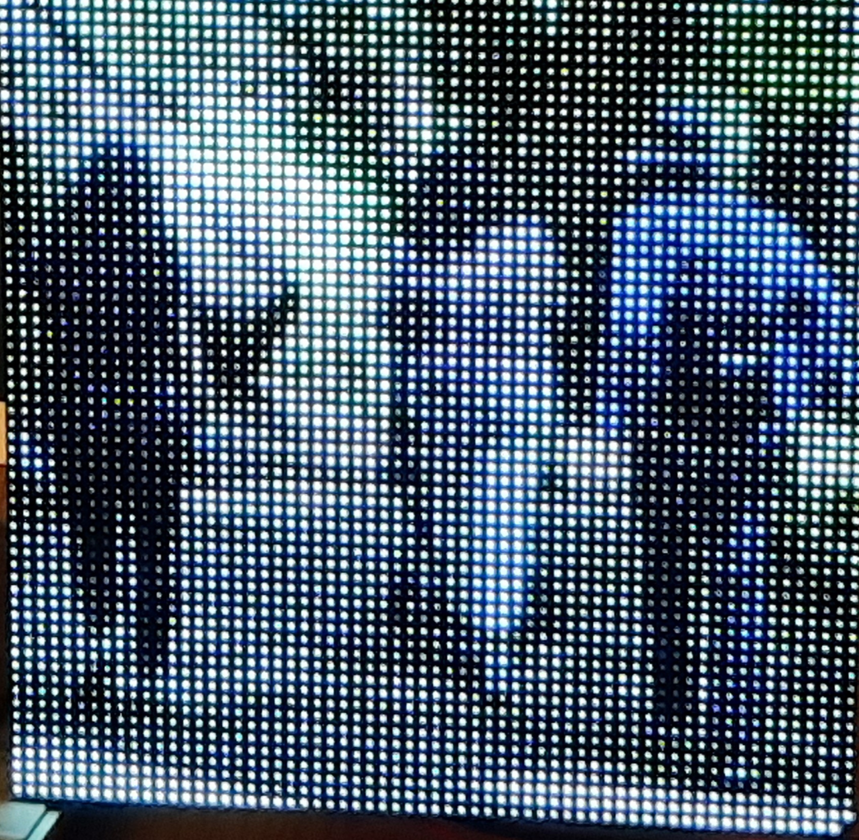
Deploying images on these LED displays is cool. You just kind of have to see it. It’s hard to describe why. The picture below does not do it justice. Think stadium scoreboard.
In rpi-rgb-led-matrix/utils directory we followed the steps in the README.md file to compile the LED viewer:
sudo apt-get update
sudo apt-get install libgraphicsmagick++-dev libwebp-dev -y
make led-image-viewer
#!/bin/sh

# invert images because the sound stuff is otherwise upside-down

sudo led-image-viewer –led-pixel-mapper=”U-mapper;Rotate:180″ –led-gpio-mapping=adafruit-hat –led-cols=64 –led-rows=64 /home/pi/walk-in-the-woods.jpg
Do we have flicker? Just a tiny bit. You wouldn’t notice it unless yuo were staring at it for a few seconds, and even then it’s just isolated to a small section of the display. Probably shoddy soldering – we are total amateurs.
Tip for your images
Consider that you only have 64 x 64 pixles to work with. So crop your pictures beforehand to focus on the most interesting aspect – people if there are people in the picture (like we’ve done in the above image), specifically faces if there are faces. Otherwise everything will just look like blurs and blobs. You yourself do not have to resize your pictures down to 64 x 64 – the led software will do the resizing. So just focus on cropping down to a square-sized part of the picture you want to draw attention to.
Real-time audio
So my friend got a USB microphone. I developed the following script to make the python example work with real-time sounds – music playing, conversatiom, whatever. It’s really cool – just the slightest lag. But, yes, the LEDs bounce up in response to louder sounds.
So in the directory rpi-rgb-led-matrix/bindings/python/samples I created the script drjexample.sh.
#!/bin/sh
# DrJ 6/21
# make the LED react to live sounds by use of a USB microphone
# I am too lazy to look up how to make the python program read from STDIN so I will just
# make the equivalent thing by creating test.wav as a nmed pipe. It's an old linux trick.

rm test.wav; mkfifo test.wav

# background the python program. It will patiently wait for input
sudo python spectrum_matrix.py &

# Now run ffmpeg
# see my own post, https://drjohnstechtalk.com/blog/2019/04/live-stream-to-youtube-from-a-raspberry-pi-webcam/
ffmpeg \
-thread_queue_size 4096 \
-f alsa -i plughw:1,0 \
-ac 2 \
-y \
test.wav
So note that by having inverted the image (180 degree rotation) we have the sounds bars and images both in the same direction so we can switch between the two modes.
I believe to get the python bindings to work we needed to install some additional python libraries, but that part is kind of a blur now. I think what should work is to follow the directions in the README.md file in the directory rpi-rgb-led-matrix/bindings/python, namely
sudo apt-get update && sudo apt-get install python2.7-dev python-pillow -y
make build-python
sudo make install-python
Hopefully that takes care of it. For sure you need numpy.
Future project ideas
How about a board that normally plays a slideshow, but when the ambient sound reaches a certain level – presumably because music is playing – it switches to real-time sound bar mode?? We think it’s doable.
Recipe for a broken hat
For the LED matrix display we got the DFRobot one since that’s what was linked to in the project guide. But the thing is, the reviewer’s write-up is incomplete so what you need to do involves a little guesswork.
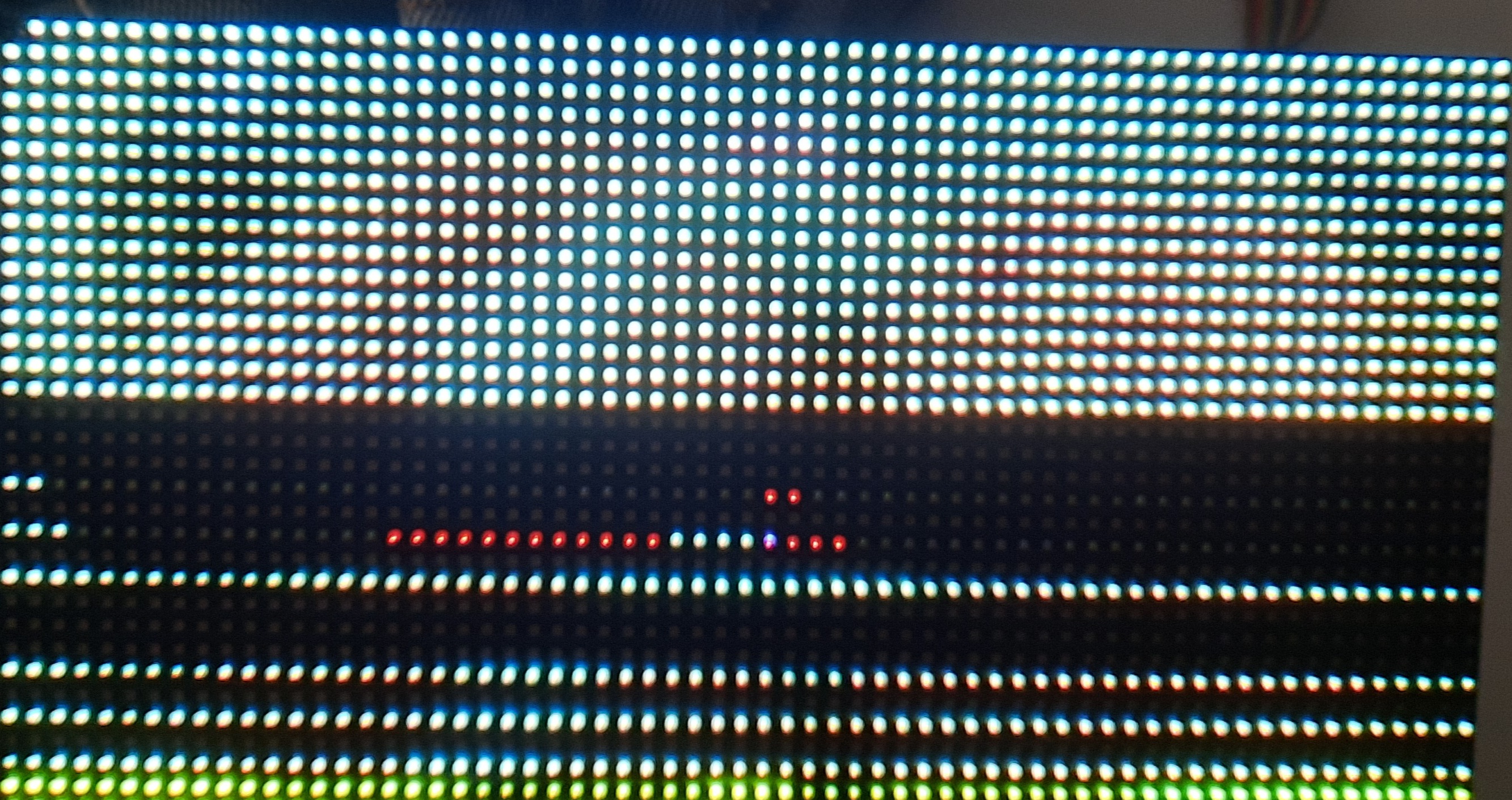
At the end of the day all we could salvage while we wait for a new Adafruit hat to come in is the top fourth of the display! The band below it is either blank, or if we push on the cables a certain way, an unreliable duplicate of the top fourth.
The next band suffers from a different problem. Its blue is non-functional. So it’s no good…
And the last band rarely comes on at all.
OK? So we’re down to a 16 x 64 pixel useable area.
But despite all those problems, it’s still kind of cool, I have to admit! I know at work we have these digital sign boards and this reminds me of that. So first thing I did was to create a custom banner – scrolling text.
I call this display program drjexample2.sh. I put it in the directory rpi-rgb-led-matrix/examples-api-use
#!/bin/sh

# DrJ – 6/21

# nice example

sudo ./demo -D1 –led-rows=64 –led-cols=64 –led-multiplexing=1  –led-brightness=50 -m25 /home/pi/pil_text.ppm
But that requires the existence of a ppm file containing the text I wanted to scroll, since I was working by example. So to create that custom PPM file I created this python script.
#!/usr/bin/python3

from PIL import Image, ImageDraw, ImageFont
# our fonts

###fnt = ImageFont.truetype(“/usr/share/fonts/truetype/dejavu/DejaVuSans-Bold.ttf”, 14)

fnt = ImageFont.truetype(“/usr/share/fonts/truetype/dejavu/DejaVuSans.ttf”, 16)

fnt36 = ImageFont.truetype(“/usr/share/fonts/truetype/dejavu/DejaVuSans-Bold.ttf”, 36)

fnt2 = ImageFont.truetype(“/usr/share/fonts/truetype/dejavu/DejaVuSans.ttf”, 18)

fntBold = ImageFont.truetype(“/usr/share/fonts/truetype/dejavu/DejaVuSans-Bold.ttf”, 40)
###img = Image.new(‘RGB’, (260, 30), color = (73, 109, 137))

img = Image.new(‘RGB’, (260, 30), color = ‘black’)
d = ImageDraw.Draw(img)

###d.text((0,0), “Baby, welcome to our world!!!”, font=fnt, fill=(255,255,0))

d.text((0,0), “Baby, welcome to our world!!!”, font=fnt, fill=’yellow’)
#img.save(‘pil_text.png’)

img.save(‘pil_text.ppm’, format=’PPM’)
Once I discovered the problem with the bands – by way of running all the demos and experimenting with the arguments a bit – I noticed this directory: rpi-rgb-led-matrix/utils. I perked right up because it held out the promise of displaying jpeg images. Anyone who has seen any of my posts know that I am constantly putting out raspberry pi based photo displays in one form or another. For instance see https://drjohnstechtalk.com/blog/2021/01/raspberry-pi-photo-frame-using-the-pictures-on-your-google-drive-ii/
or
But see how cool it is? No? It’s a sleeping, recumbent baby. It’s like the further away from it you get, the clearer it becomes. Trust me in person it does look good. And it feels like creating one of those bright LED displays they use in ballparks.
But this same picture also shows the banding problem.
To get the picture displayed I first cropped it to make it wide and short. I wisely chose a picture which was amenable to that approach. I created this display script:
#!/bin/sh

sudo led-image-viewer –led-no-hardware-pulse –led-gpio-mapping=adafruit-hat –led-cols=64 –led-rows=64 –led-multiplexing=1 /home/pi/baby-sleeping.jpg
But before that can all work, you need to compile the program. Just read through the README.md. It gives these instructions which I followed:
sudo apt-get update
sudo apt-get install libgraphicsmagick++-dev libwebp-dev -y
make led-image-viewer
It went kind of slowly on my RPi 3, but it worked without incident. When I initially ran the led-image-viewer nothing displayed. So the script above shows the results of my experimentation which seems appropriate for our particular matrix display.
How did we get here?
Just to mention it, we followed the general instructions in that project. So I guess no need to repeat the recipe here.
Slideshow
You know I’m not going to let an opportunity to create a slideshow go to waste. So i created a second appropriately horizontal image which I might effectively show in my narrow available band of 16 x 64 pixels. just to share the little script, it is here:
#!/bin/sh

cd /home/pi

sudo led-image-viewer –led-no-hardware-pulse –led-gpio-mapping=adafruit-hat –led-cols=64 –led-rows=64 –led-multiplexing=1 -w6 -f baby-and-mom.jpg baby-sleeping.jpg
This infinitely loops over two pictures, displaying each for six seconds.
Start on boot
I have the slideshow start on boot using a simple technique I’ve developed. You edit the crontab file (crontab -e) and enter at the bottom:
@reboot sleep 35; /home/pi/rpi-rgb-led-matrix/utils/jdrexample2.sh > drjexample.log 2>&1
Lessons learned
My friend ordered all the stuff listed on the DFRobot project page, including their 64×64 LED matrix. Probably a mistake. They basically don’t document it and refer you to Adafruit, where they deal with a 64×64 LED matrix – their own – which may or may not have the same characteristics, leaving you somewhat in limbo. Next time I would order from Adafruit.
As mentioned above that gold foil on printed circuit boards really does come off pretty easily, and then you’re hosed. Because of the lack of technical specs we were never really sure if we needed to solder the E contact to 8 or to 16 and destroyed all those terminals in the process of backing out.
I actually created custom ppm files of solid colors, red, blue, green, white, so that I could prove my suspicions about the third band. Red and green display fine, blue not at all. White displays as yellow.
Viewed close up, the LED matrix doesn’t look like much, and of course I was close up when I was working with it. But when I stepped back I realized how beautiful a brightly illuminated picture of a baby can be! The pixels merge and your mind fills in the spaces between I guess.
The original idea was to tackle sound but I got stuck on the ability to use it as a photo frame (you know me). But he wants to return to sound which I am dreading….
Testing audio
In our first tests. the audio example wasn’t working. But now it seems to be. The project guy’s python code is named spectrum_matrix.py if I recall correctly. It goes into rpi-rgb-led-matrix/bindings/python/samples. And as he says, you run it from that directory as
$ sudo python spectrum_matrix.py
But, his link to test.wav is dead – yet another deficiency in his write-up. At least in my testing not every possible WAV file may work. This one, moo sounds, does however. http://soundbible.com/grab.php?id=1778&type=wav So, it plays for a few seconds – I can hear it through earphones – and the LEDs kind of go up and down. We recorded a wav file and found that that does not work. The error reads like this:
Home directory not accessible: Permission denied
W: [pulseaudio] core-util.c: Failed to open configuration file '/root/.config/pulse//daemon.conf': Permission denied
W: [pulseaudio] daemon-conf.c: Failed to open configuration file: Permission denied
Traceback (most recent call last):
File "spectrum_matrix.py.orig", line 56, in
matrix = calculate_levels(data,chunk,sample_rate)
File "spectrum_matrix.py.orig", line 49, in calculate_levels
power = np.reshape(power,(64,chunk/64))
File "/usr/lib/python2.7/dist-packages/numpy/core/fromnumeric.py", line 292, in reshape
return _wrapfunc(a, 'reshape', newshape, order=order)
File "/usr/lib/python2.7/dist-packages/numpy/core/fromnumeric.py", line 56, in _wrapfunc
return getattr(obj, method)(*args, **kwds)
ValueError: cannot reshape array of size 2048 into shape (64,64)
Note that I had renamed the original spectrum_matrix.py to spectrum_matrix.py.orig because we started messing with it. Actually, I pretty much get the same error on the file that works; it’s just that I get it at the end of the LED show, not immediately.
Superficially, the two files differ somewhat in their recording format:
$ file ~/voice.wav moo.wav
/home/pi/voice.wav: RIFF (little-endian) data, WAVE audio, Microsoft PCM, 16 bit, mono 44100 Hz
moo.wav: RIFF (little-endian) data, WAVE audio, Microsoft PCM, 16 bit, stereo 32000 Hz
I played the voice.wav on a Windows PC – it played just fine. Just a little soft.
So what’s the essential difference between the two files? Well, something that jumps out is that the one is mono, the other stereo. Can we somehow test for that? Yes! I made the simplest possible conversion af a mono to a stereo file with the following ffmpeg command:
$ ffmpeg -i ~/voice.wav -ac 2 converted.wav
$ file converted.wav
converted.wav: RIFF (little-endian) data, WAVE audio, Microsoft PCM, 16 bit, stereo 44100 Hz
I copy converted.wav to test.wav and re-run spectrum_matrix.py. This time it works!
Not sure how my friend produced his wave file. But I want to make one on my own. He had plugged a USB microphone into the RPi. I have done research somewhat related to this – publishing a livestream to Youtube, audio only, video grayed out. That’s in this post: https://drjohnstechtalk.com/blog/2019/04/live-stream-to-youtube-from-a-raspberry-pi-webcam/ So I am not afraid to se ffmpeg any longer. So I created this tiny script, record.sh, with my desired arguments:
#!/bin/sh

# see my own post, https://drjohnstechtalk.com/blog/2019/04/live-stream-to-youtube-from-a-raspberry-pi-webcam/

ffmpeg \

-thread_queue_size 4096 \

-f alsa -i plughw:1,0 \

-ac 2 \

/tmp/ffmpeg.wav
And I ran it while speaking loudly into the mic. It ran OK. The output file comes out as
test.wav: RIFF (little-endian) data, WAVE audio, Microsoft PCM, 16 bit, stereo 48000 Hz
And…it plays with the LEDs dancing. Great.
Audio: LED responds to live input
My friend wants the LED to respond to live input such as his stereo at home. Being a terrible python programmer but at least middling linux techie, I see a way to accomplish it without his having to touch the sample program by employing an old Unix trick: named pipes. So I create this script, drjexample.sh which combines all the knowledge we gained above into one simple script:
#!/bin/sh
# DrJ 6/21
# make the LED react to live sounds by use of a USB microphone
# I am too lazy to look up how to make the python program read from STDIN so i will just
# make the equivalent thing by creating test.wav as a nmed pipe. It's an old linux trick.

rm test.wav; mkfifo test.wav

# background the python program. It will patiently wait for input
sudo python spectrum_matrix.py &

# Now run ffmpeg
# see my own post, https://drjohnstechtalk.com/blog/2019/04/live-stream-to-youtube-from-a-raspberry-pi-webcam/
ffmpeg \
-thread_queue_size 4096 \
-f alsa -i plughw:1,0 \
-ac 2 \
-y \
test.wav
So a named pipe is just that. Instead of the pipe character we know and love, you coordinate process output from the first process with process input of the second process by way of this special file. The operating system does all the hard work. But it works just as though you had used the | character.
Best of all, this script actually works, to wit, the LED is now responding to live input. I see it jump when I say test into the microphone. Unknown to me is if it will play for extended periods of time – it would be easy for one process to output faster than the other can input for instance, so a backlog builds up. The responsiveness is good, I would guess around no more than 200 ms lag.
Equipment
We used the equipment from this post, except the Firebeetle. You know, that’s just another reason I consider that post to be a sloppy effort. Who lists a piece of equipment that they don’t use?? And again, next time I would rather search for an LED display from Adafruit. We use an RPi 3 and installed the image on a micro SD card with the new-ish Raspberry Pi imager, which works just great: Introducing Raspberry Pi Imager, our new imaging utility – Raspberry Pi
Oh, plus the soldering iron and solder. And a multi-colored ribbon cable with female couplers at one end and a 2×8 connector on the other. Not sure if that came with the LED or not since I didn’t order it.
Our power supply is about 5 amps and plugs into the hat. We do not need power for the RPi.
References and related
This post makes it seem like a walk in the park. Our experience is not so much. Raspberry Pi Audio Spectrum Display – Hackster.io
People seem to like this Raspberry Pi photo frame post I did which draws photos from your Google drive. https://drjohnstechtalk.com/blog/2020/12/raspberry-pi-photo-frame-using-your-pictures-on-your-google-drive/
Introducing Raspberry Pi Imager, our new imaging utility – Raspberry Pi – for putting the operating system formerly known as Raspbian onto a micro SD card.
test.wav (Use this moo wav file and rename to test.wav): http://soundbible.com/grab.php?id=1778&type=wav
Useful ffmpeg commands: FFmpeg Commands: 31 Must-Haves for Beginners in 2022 – VideoProc
Or 20+ FFmpeg Commands For Beginners – OSTechNix
How I figured out hot to livestream audio to YouTube without video from a RPi using ffmpeg is documented here: https://drjohnstechtalk.com/blog/2019/04/live-stream-to-youtube-from-a-raspberry-pi-webcam/
Github project for this effort (not completely working as of yet):